“I always wondered what Mome Raths sound like when they outgrabe. Now I know. Thank you!” - Carol Lewis
Introduction
In latter model synthesizers, digital noise sources began to appear in place of analog ones. Traditionally, a psuedo-random shift register set up for optimal length. By optimal length, it is meant that every state of all available bits will appear at some time, but the order is unknown. Essentially a counter that counts in an unknown order. This represents the maximum state of information “entropy” available for that number of bits.
But music has close self-similarity over short periods of time. That is, it repeats itself with changes appearing slowly. This shift register generator is designed to give control of the rate of appearance of new information. It has a tight set of controls over how random it actually is and how fast change occurs.
Tone Wheels and Noise Rings
Clocked at audio rates, the shift register forms a kind of synthetic “tone wheel”, similar in idea to the electromechanical tone wheels in organs. But with very crude quantization, and hence very “noisy”. To some extent you can visualize the resistor summers (DACS - digital to analog converters) like the lines of magnetic force around a metallic tone wheel. Different summers form different kinds of pickups. It is actually a digital transversal filter, but the “pickup” idea is helpful.
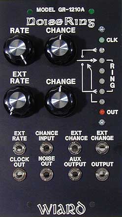
All voltage ranges are from 0 to 10 volts. The Aux Output (n+1) will change between one of 9 voltage levels. The Output (2^n) will change between one of 256 voltage levels.
Noise Source
The module contains an internal analog white noise generator. Random digital data is generated by using two comparators to compare the noise voltage against two DC voltages. One comparator generates a controllable density of zeros or ones. The second comparator controls the solid state switch which which selects between recycling old data in the shift register, or getting new data from the outside. If the “CHANGE” control is set to 100%, ALL new data is shifted through the register. With the “CHANGE ” control set to 0%, only old data is recycled through the shift register without change.
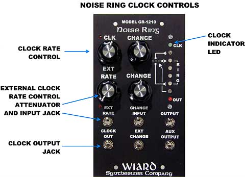
Clock
A wide range voltage controlled oscillator is used to clock the shift register. The 4 decade range from 1 Hertz to 10 Kilohertz, allows the generation of audio rate sound and also control voltage sequences. The VCO has a coarse set front panel control and an external control voltage input with attenuator.
- Clock frequency is nominally 1 Hz to 10 kHz. 0 to +10 V square wave.
- Green “CLK” LED flashes when “CLOCK OUT” jack is at +10V.
- The “n+1” output is normalized to the “EXT RATE” input. Increasing the “EXT RATE” control randomizes the clock time.
- If an external voltage source is connected to the “EXT RATE” input jack, the “n + 1” connection is broken.
“CHANCE” Control
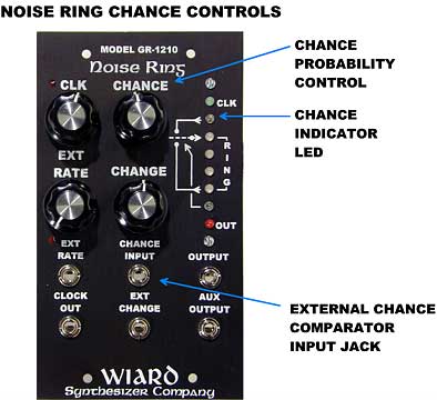
Chance controls the number of zeros and one extracted from the noise source.
- At 7 o’clock position, all zeros are output and the “Chance indicator” LED is always off.
- At 5 o’clock position, all ones are output and the “Chance indicator” LED is always on.
- At 12 o’clock position, equal numbers of zeros and ones are output and the “Chance indicator” LED flickers.
With the “CHANGE” control is set to 100% (all new data), sweeping the “CHANCE” control sounds like Chance Sweep — 2^n Output at the 2^n output
With the “CHANGE” control is set to 100% (all new data), sweeping the “CHANCE” control sounds like Chance Sweep — n+1 Output at the n+1 output
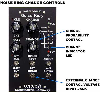
”CHANGE” Control
Change controls the number of new zeros and one which are let into the ring.
- At 5 o’clock position, all old data is used and the “Change Indicator” LED is always off.
- At 7 o’clock position, all new data is used and the “Change Indicator” LED is always on.
- At 12 o’clock position, equal numbers of old and new data are used and the “Change Indicator” LED flickers.
NOISERING OUTPUTS and LEDs
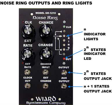
-
The “n” ring lights flicker red and green as data passes through the ring.
-
The orange “OUT” LED will change brightness with the 2^n output voltage.
Processing External Data
Oscillator:
Another oscillator can be used to supply data into the shift register. Connect any waveform into the “CHANCE INPUT” jack. In this case we Swept Shift Register — Phased the familiar “phased” sound of a swept shift register
At ultrasonic frequencies the heterodynes Ultrasonic Heterodyne — Shortwave
Drum Machine:
Drum Machine Through NoiseRing the drum machine input is processed through the NoiseRing, then has the envelope reapplied to a VCF
Information from the Internet Archive wayback machine of the relevant Wiard 1200 page